Roland DXY 990 pen plotter #
I’ve been interested in pen plotters for quite a while, probably because it’s often used in the “generative art” space that I’ve been dabbling with since forever. The last year or so my interest increased and I took a serious look at my options. I weighed buying a brand new modern machine, getting a DIY kit, and actually building one myself from scratch (would be a big learning project). But then I saw a post about an old Roland plotter from the 80s, and got really intriguied - I checked my local craigslist alternative and found a Roland DXY 990 in good condition for sale! Surely a sign, so I had to buy it. Here I’ll write up my journey to use it with Processing on my Windows PC (might do a follow up with macos or linux as well).
Background info
The Roland can communicate via its serial port. It speaks a language/file format called HPGL (Hewlet Packard Graphics Language). HPGL is pretty awesome, has an open spec/manual, and a lot of vector drawing software can export to this format.
Hardware setup
Ok so setting up the hardware bits turned out to be the easier part. This Roland DG DXY-990 hackaday project has a lot of extremely useful information, basically everything you need to know. Without seeing this page I may not have dared to buy the device. My set up is similar, but I will write it down here as it could still be useful for others:
- I got an off the shelf RS-232 DB9 male to USB cable from swedish chain store Kjell&Company (this one to be precise).
- Since the Roland machine has a DB25 serial port I also need a converter. I bought a 2 meter 25-pin male to 9 pin female (this one)
Included in the Roland box I got a serial DB25 male to female. So my first attempt included three cables: PC -> (USB to 9 pin serial) -> (9 to 25 pin) -> (included cable) -> Roland. This did not work, basically no data seemed to arrive to the plotter. I removed the old, included cable from the chain just to try and that did the trick. So the final connection chain I use is:
PC -> (USB to 9 pin serial) -> (9 to 25 pin) -> Roland
To test the communication I tried a few tools, but the most useful was simple command line stuff. In windows I used mode and echo:
mode com6:9600,e,7,1,p
echo in;sp1;pd4000,4000;sp0;pg; >com6
The mode command allows us to configure the port. Exactly what settings we should use depends on the dip switch configuration on the Roland device itself.
I ended up using this configuration (derived from rawe’s hackaday recommendation) of the Roland switches:
                            SW-1                                                         SW-2
  10    9     8     7     6     5     4     3     2     1             8     7     6     5     4     3     2     1
+---+ +---+ +---+ +---+ +---+ +---+ +---+ +---+ +---+ +---+         +---+ +---+ +---+ +---+ +---+ +---+ +---+ +---+
|   | |   | |   | |   | |   | |   | |   | |   | |   | |   |         |   | |   | |   | |   | |   | |   | |   | |   |
| ^ | | ^ | | | | | ^ | | ^ | | | | | ^ | | ^ | | ^ | | ^ |         | ^ | | | | | | | | | | | ^ | | ^ | | ^ | | | |
| | | | | | | | | | | | | | | | | | | | | | | | | | | | | |         | | | | | | | | | | | | | | | | | | | | | | | |
| | | | | | | | | | | | | | | | | | | | | | | | | | | | | |         | | | | | | | | | | | | | | | | | | | | | | | |
| | | | | | | | | | | | | | | | | | | | | | | | | | | | | |         | | | | | | | | | | | | | | | | | | | | | | | |
| | | | | | | v | | | | | | | | v | | | | | | | | | | | | |         | | | | v | | v | | v | | | | | | | | | | | v |
|   | |   | |   | |   | |   | |   | |   | |   | |   | |   |         |   | |   | |   | |   | |   | |   | |   | |   |
+---+ +---+ +---+ +---+ +---+ +---+ +---+ +---+ +---+ +---+         +---+ +---+ +---+ +---+ +---+ +---+ +---+ +---+
Here arrow up = OFF, and arrow down = ON (the numbers on the back of the machine are upside down compared to my ascii drawing). Switches 8+7 on SW-1 controls paper size/format, I’m using ISO A3 here (afaik). See the Roland DXY-990 manual for details.
After confirming that I could communicate with the plotter with some super basic HPGL commands, I tried plotting something a little more advanced and immediately got into the next problem.
Inconsistent lines
The drawing I sent to the plotter consisted of some pie-like shapes, kind of like a deconstructed pie chart:
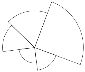
I figured my “Kaynting” processing sketch was going to be my first real test of the plotter. But the plotting of this looked pretty bad, the arc lines contained gaps.
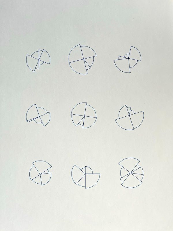
I played around with all kinds of things, mostly involving the “pen force” knob on the machine but eventually I realized that it could be due to the drawing speed.
Sure enough after lowering to “speed 2” (HPGL command VS2;) instead of 5 or whatever, the arcs looked solid. Cool, now I wanted to draw multiple similar shapes on the same paper. On to the next problem, that took much longer to solve.
Software, flow control, and communication
As soon as I sent a bigger file to the plotter it started acting strange. I had configured the com6 port in my usb settings to match the dip switches (7 bits, 1 stop bit, xon/xoff flow control, etc).
But the plotter didn’t do anything, the sending was blocked after the two first lines. This problem persisted even after power cycling my Roland boy. I fumbled around a lot when this happened, I didn’t at all connect this behavior to the bigger file, and I think I even tried some very basic, small test HPGL commands with the same result at this point so it was frustrating.
Now is a good time to specify exactly how I send data to the plotter. This is interesting because it shows how to generate HPGL with processing and send it to the serial port. There will be a mix of java and clojure (because I love Quil).
Processing to HPGL commands
I use and really recommend the hpglgraphics library.
HPGLGraphics hpgl;
...
void setup() {
  hpgl = (HPGLGraphics) createGraphics(width, height, HPGLGraphics.HPGL);
  hpgl.setPaperSize("A3");
  ...
}

void saveHPGL(String filename) {
  hpgl.setPath(filename);
  beginRecord(hpgl);
    hpgl.setSpeed(2); // Optional, but ensure lines like arcs etc look consistent/solid
    render(); // This is your custom processing render code, using all the normal stuff like line, rotate, pop/pushMatrix, translate etc.
  endRecord();
}
And then I call saveHPGL on some key press when the sketch looks good.
Writing to serial port with jSerialComm
Processing comes with built-in serial I/O functionality, but I noticed it lacked some features (like specifying exact settings), so I opted to use jSerialComm right away. Here’s an excerpt of my Quil clojure code to write a HPGL file:
(ns write-hpgl.core
  ...
  (:import [com.fazecast.jSerialComm SerialPort]
           [java.io File BufferedReader FileReader OutputStreamWriter BufferedWriter]))

;; Example usage: (send-hpgl "COM6" "foo.hpgl")
(defn send-hpgl
  [port-name filepath]
  (let [port (SerialPort/getCommPort port-name)]
    (.setComPortParameters port 9600 7 SerialPort/ONE_STOP_BIT SerialPort/EVEN_PARITY)
    (.setFlowControl port
                     (bit-or SerialPort/FLOW_CONTROL_XONXOFF_IN_ENABLED
                             SerialPort/FLOW_CONTROL_XONXOFF_OUT_ENABLED))
    (println "Flow control mode:" (.getFlowControlSettings port))

    (if-not (.openPort port)
      (println "Failed to open port" port-name)
      (try
        (with-open [reader (BufferedReader. (FileReader. (File. filepath)))
                    writer (BufferedWriter. (OutputStreamWriter. (.getOutputStream port)))]
          (doseq [line (line-seq reader)]
            (println line)
            (.write writer line)
            (.flush writer)
            (Thread/sleep 10))
          (println "HPGL file sent successfully."))
        (finally
          (.closePort port))))))
At this point I decided to limit the amount of variables and context switching I had to do, so I ported the above code to java and stayed in the default processing environment. I started suspecting that the flow control settings (xon/xoff) was related to my problem because if I switched it off the plotter started working on the first instructions it got immediately. But it still only handled the first few commands, and then the Error LED on the device blinked.
With this in mind I tried to re-enable xon/xoff, and see if I got some lines from Roland boy instructing me to pause sending (XOFF). Basically, I checked whether the port’s input stream had any available data, and if so is it XOFF (ASCII 19)? Then pause for a bit, if we get XON (ASCII 17) - continue. I implemented this but I never got anything in the inputstream :(
I was starting to get desperate so I looked into an existing (python) library that is made for communicating with old plotters: chiplotle3. And thank goodness for that! Here I learned about its clever communication & flow control technique; ask the plotter about its current buffer size before sending anything, if it’s above a certain size go ahead, if not wait a bit and repeat.
The cool thing is that HPGL itself has an escape code to ask for the buffer size: "?.B", and Roland boy will answer back with the number of free bytes. I implemented this and turned off flow control for the port - success!
Feels good to see a version of this rather old (10+ years) sketch on some physical material.
Obligatory video (sound on hehe):
One explanation for having to do this myself instead of relying on the flow control setting (which I assumed would do pretty much the same thing) is because the driver for the USB-to-serial cable may or may not handle flow control properly.
Next steps
- Automatically vary pen speed depending on the type of drawing primitive (e.g lines can be faster than arcs)
-
HPGL optimizer, ensure plotter doesn’t draw the same area twice. E.g if file contains line1:
(0, 0) -> (100, 0)and line2:(50, 0) -> (110, 0)replace those with just(0, 0) -> (110, 0) -
Publish code for my helper library JAR that contains the
sendHPGLWithBackoff(and other utilities), which makes it easy to reuse for all my processing/quil sketches - Plot the next sketch!